Medical and Technical Background#
Carpal Tunnel Syndrome#
Carpal tunnel syndrome (CTS) is the most common condition of peripheral nerve entrapment worldwide [3] . It is an entrapment nephropathy, a damage to the nerve in the regions where it passes through narrow spaces. Even if just a small region of the nerve is damaged, neuropathies can have a significant impact physically, psychologically, and economically, since they can lead to a loss of function of the affected areas and a disability to fulfill simple daily tasks [3] .
The carpal tunnel condition occurs when the median nerve, one of the major nerves to the hand, is squeezed or compressed as it travels through the wrist. The symptoms are pain, numbness, and tingling in the hand and arm, and they can be classified into mild, moderate, or severe cases [4]. The elderly population is the most affected by the condition, and it is most prevalent in women compared to men [5] . It is highly correlated to work activities that cause strain and repetitive movements, as well as extended positions in excesses of wrist flexion or extension, monotonous use of the flexor muscles, and exposure to vibration:footcite:Geoghegan.2004 . Compression may occur from space-occupying lesions on the wrist or mechanical stress of the nerve caused by contact with the surrounding tendons. The incidence rate might also increase for some specific categories such as cyclists, wheelchair users, wrestlers, or extensive computer users [6]. CTS may moreover be associated with hypothyroidism, diabetes menopause, obesity, arthritis, and pregnancy, which makes suspect relations not only to mechanical damage but also to hormonal changes [3] .
The pathophysiology of CTS comprises a combination of mechanical trauma, elevated pressure in the carpal tunnel, and ischemic damage to the median nerve. In most patients, it worsens over time, so early diagnosis and treatment are important. The first symptoms of the illness are sporadic, nighttime paraesthesias and dysaesthesias that become more frequent and happen during the day. Later in the course of the disease, loss of feeling, weakness, and muscle atrophy follow, all of which are caused by severe axonal degeneration [7] . Early on, symptoms can often be relieved with simple measures like wearing a wrist splint or avoiding certain activities. However, more severe cases need surgical interventions, such as open release and endoscopic surgeries.
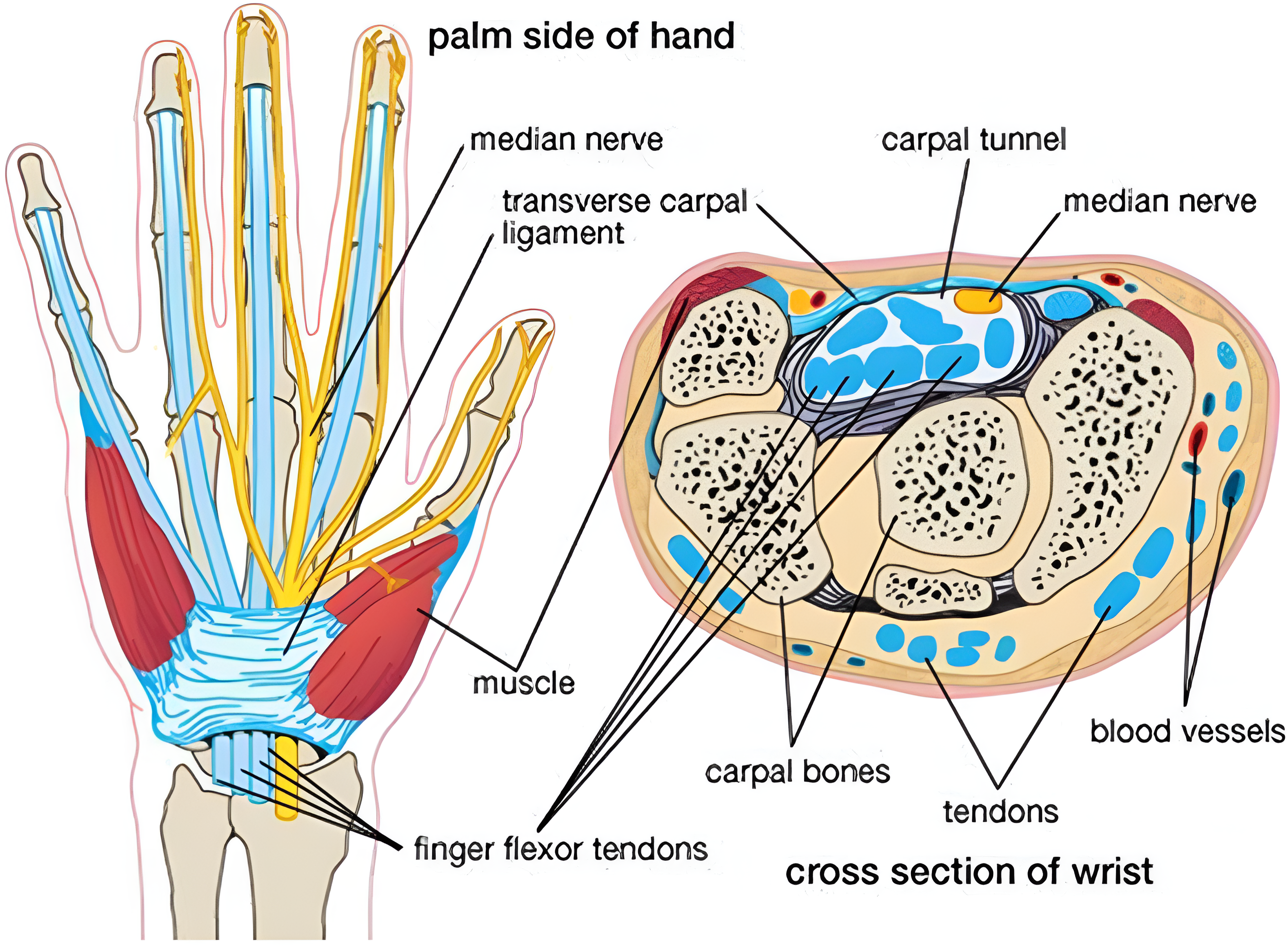
Fig. 1 Figurative structure of the carpal tunnel and of the median nerve branches. Figure from [8].#
Carpal Tunnel Anatomy#
The carpal tunnel is a narrow passageway located on the palm side of the wrist, and its anatomy can be visualized in Fig. 1. It is defined by the flexor retinaculum on the top, which forms a roof over the tunnel, and the carpal sulcus on the bottom. The carpal bones delimiting the tunnel at the ulnar edge are the hamate hook, the pyramidal bone, and the psiform bone, while the radial edge is formed by the scaphoid bone, the trapezoid bone, and the tendons of the flexor carpi radialis (FCR) muscles. The bones at the base are the underlying portions of the scaphoid, lunate, capitate, hamate, trapezium, and trapezoid.
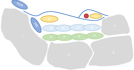
Fig. 2 Simplified transversal structure of the carpal tunnel. 1 - Scaphoid bone; 2- Lunate bone; 3 - Triquetrum bone; 4 - Psiform bone; FCR - flexor carpi radialis; FPL - Flexor pollicis longus; S - Flexor superficialis tendons; P - Flexor profundus tendons; M - Median nerve; U - Ulnar nerve. Figure adapted from [6] .#
The median nerve, which controls sensation and movement in the thumb and first three fingers, runs through this passageway along with the superficial tendons of the fingers and the long flexor of the thumb. After the tunnel, the nerve divides into six different branches. Nonetheless, the anatomy of the nerve may present some variations, which explain the different symptoms and make the diagnosis more difficult [5] .
CTS Diagnosis#
The diagnosis of CTS is usually based on the history of the patient associated with the characteristics of the condition. The patients are usually asked to describe their symptoms and their frequency. In addition, the physician may inquire about the patient’s daily activities, work, and hobbies, as well as any medical conditions to asses any predisposing factors [9] .
Thereafter, the physician may perform a physical examination, which includes specific tests and maneuvers to assess the function of the median nerve and the control and strength of the hand motor functions [10] . If the patient’s medical history, symptoms, and physical examination lead to a CTS suspect, further examinations are conducted to confirm the diagnosis, determine the severity, and plan the treatment. A comparison between the different diagnostic techniques is summarized in [tab:diagnostic].
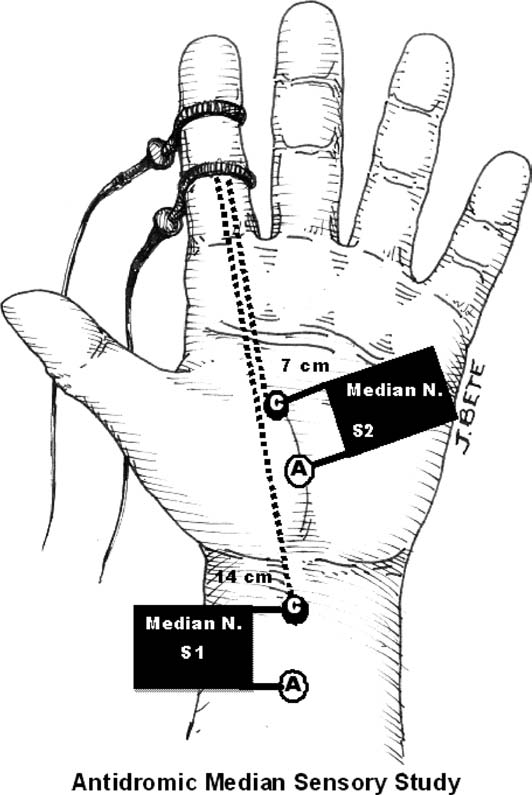
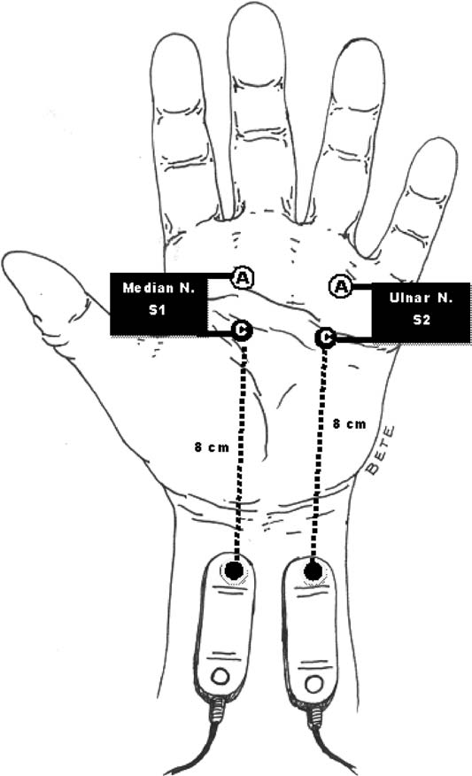
A standard diagnostic procedure for CTS is the electrodiagnostic testing, which consists in measuring the electrical conductivity of the nerve along its three main branches. It helps to assess quantitatively the severity of entrapment, but it is prone to false negatives and false positives, it is time-consuming and it does not give any insight into the anatomy of the carpal tunnel.
A better and more expressive evaluation of the CTS is to measure the cross-sectional area (CSA) of the nerve, which can be visualized with medical imaging techniques. Magnetic Resonance Imaging (MRI) offers good visualization of the complete anatomy but it is expensive and time-consuming. Moreover, the accurate segmentation of the median nerve depends on the operator’s experience.
Finally, sonographic imaging has become a popular method to assess carpal tunnel syndrome since it offers real-time visualization, and is portable and accessible [11][12] . It can reach resolutions of less than 1 mm, thanks to advancements in technology such as affordable high-frequency probes, enabling the diagnosis of the CT condition by visualization of the nerve’s structure [13] . Carpal tunnel syndrome is believed to cause morphological changes to the median nerve resulting from compression by the surrounding nonrigid tissues. This effect reduces nerve volume at the site of compression while increasing size proximal (and sometimes distal) to the compression [3] . However, the operator dependency and the lack of standardization in the acquisition protocol can lead to inconsistent results [14] . Moreover, the procedure is time-consuming and requires long operator training and high expertise. Due to the low contrast of nerve tissue in the image and its low variability from other tissues, the median nerve is very difficult to segment.
Electrodiagnostic Testing |
Magnetic Resonance Imaging |
Ultrasound Imaging |
|---|---|---|
Antidromic stimulation in the palm with recording at the index finger or middle finger. |
Axial T1 evaluates the tendons of the wrist and carpal tunnel, including the flexor retinaculum. |
Positioning of the probe to analyze the median nerve at the level of the distal third of the forearm and of the carpal tunnel at the scaphoid-pisiform level. |
|
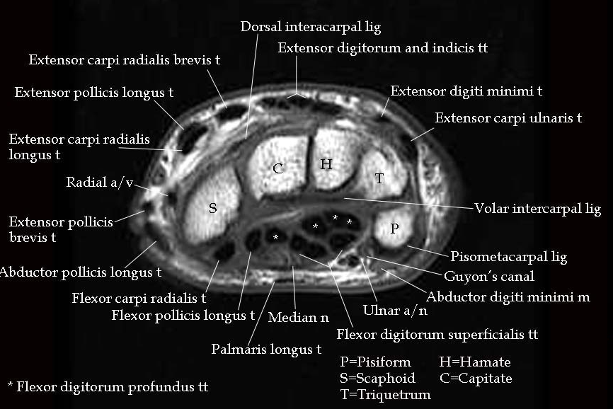
Fig. 3 MRI of the carpal tunnel at the Psiform-Scaphoid standard plane. Figure from [16].# |
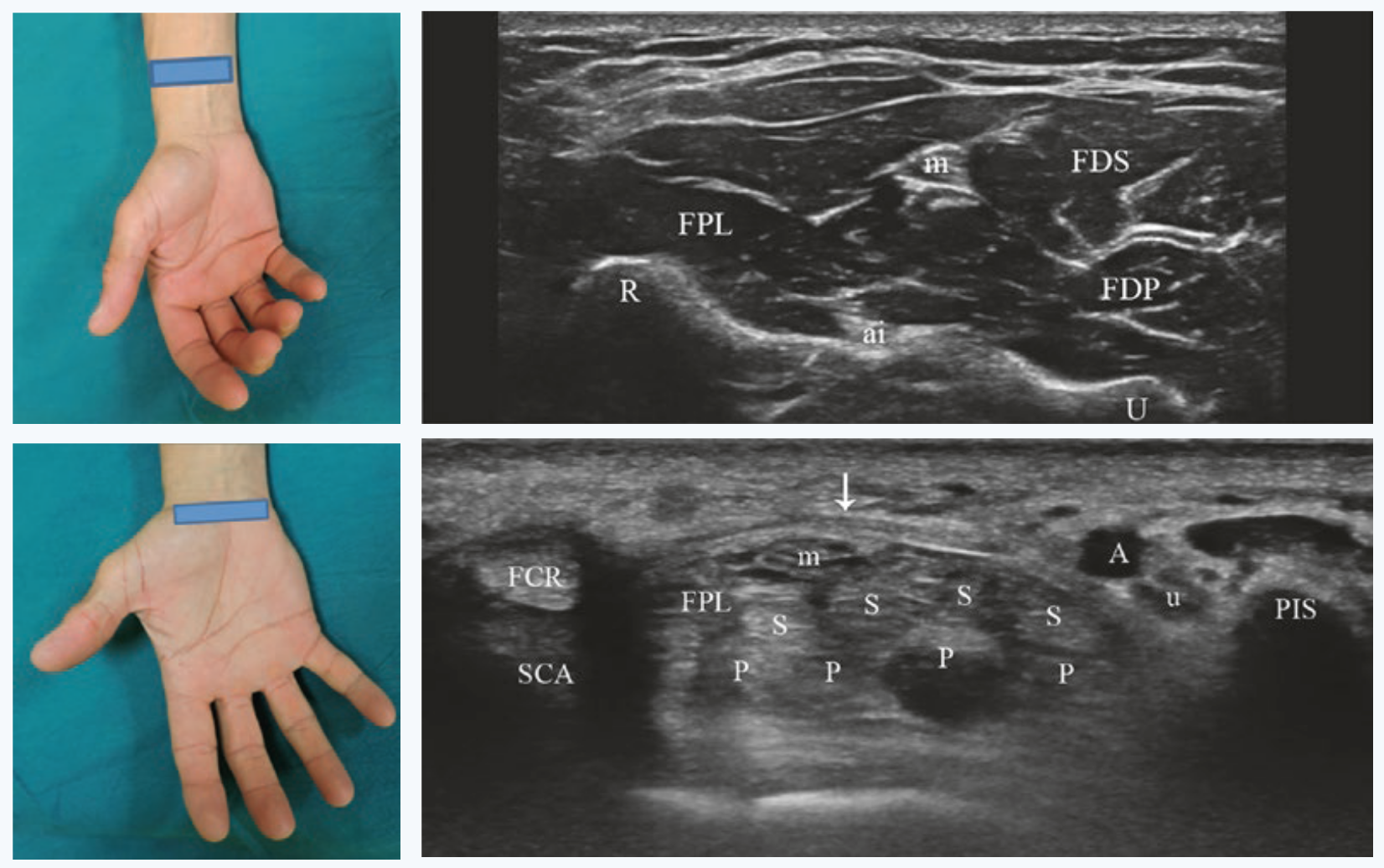
Fig. 4 Standard positions for median nerve visualization at the carpal tunnel and at distally at its free exit. Figures from [6].# |
Pros: |
||
|
|
|
Cons: |
||
|
|
|
Ultrasound Imaging#
Ultrasound imaging (US), also known as sonography, is one of the most widely used medical imaging techniques [17]. It is a non-invasive medical diagnostic technique that uses high-frequency sound waves to visualize in real time the internal human body structures including soft tissues, such as organs, musculoskeletal system, nerves, and blood flow.
Thanks to the real-time visualization, portability, absence of ionizing radiation, high sensitivity, and image resolution, US scanning applications are continuously increasing [18]. It is widely employed across various medical specialties, including obstetrics, cardiology, gastroenterology, and musculoskeletal imaging. One of the key advantages of ultrasound imaging is its safety making it particularly suitable for monitoring pregnant women and pediatric patients. The real-time nature of ultrasound allows for dynamic assessments, enabling healthcare professionals to observe moving structures and assess blood flow patterns. Additionally, ultrasound is instrumental in guiding minimally invasive procedures such as biopsies and injections.
Ultrasound Properties#
The basic principle underlying ultrasound imaging involves the emission of sound waves from a transducer, a device emitting and receiving these waves. Sound waves are characterized by frequency, wavelength, amplitude, period, velocity, power, and intensity [6]. These waves travel through the body, encountering tissues with varying acoustic properties. When the sound waves encounter a boundary between tissues of different densities, some waves are reflected to the transducer, while others continue to penetrate deeper. The returning waves are then converted into electrical signals, and sophisticated computer algorithms analyze these signals to create high-resolution images.
Nerves Ultrasound Imaging#
Peripheral nerves consist of nervous fibers composed of axons grouped into fascicles:footcite:Stewart.2003. Each fascicle is covered by the perineurium, a connective tissue layer, and the whole nerve is surrounded by the epineurium, the outermost dense sheet of connective tissue. The axons forming the fascicles are surrounded by the endoneurial fluid, which is a mixture of water, proteins, and electrolytes. The connective tissue that envelops the axon is the endoneurium. Moreover, each axon is wrapped into the myelin sheath, a lipid-rich layer produced by the Schwahn cells that insulate the axon and is responsible for the rapid conduction of nerve impulses.
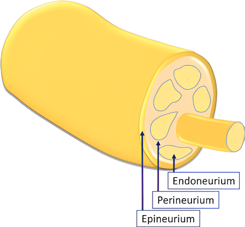
Fig. 5 Scheme depicting the inner structure of the peripheral nerve [6].#
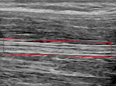
Fig. 6 Longitudinal view of the median nerve (red box) with ultrasound [6].#
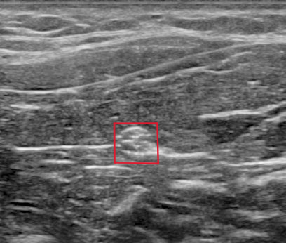
Fig. 7 Transverse view of the median nerve (red box) with ultrasound [6].#
Because of their anatomical structure, nerves present a cable-like structure recognizable in the ultrasound image, as in Fig. 5. In the longitudinal plane, nerves appear as long and thin structures, with parallel lines representing the perineurium of the axons and two noticeably thicker lines of the epineurium, as is visible in Fig. 6. In the transverse plane, nerves resemble a honeycomb of round areas, composed of the fascicles surrounded by the perineurium thicker layer, visible in Fig. 7. This is the most common view in clinical practice since it permits locating the nerve at standard positions between specific anatomical landmarks, and tracking it distally or proximally [6]. Moreover, transversal imaging displays the nerve’s shape and allows to asses its size, vasculature, and relation to the surrounding tissues.
Nerves are recognizable in US images due to their characteristic isotropy [6]. Anisotropy means that the angle of incidence equals the angle of reflection, which makes tissues look brighter with perpendicular insonation. This is a typical characteristic of tendons. Nerves, on the other hand, are isotropic, meaning that they have a uniform behavior regardless of the angle of incidence. This is because the nerve is composed of a mixture of tissues with different acoustic properties, making the reflection of the sound waves more complex.
Nerve shapes vary across individuals, including round, oval, triangular, and irregular shapes. Moreover, these can alter during a scan because of probe pressure or muscle activity. Nerves can even change form along their course and may have anatomical variations, such as the bifid or trifid versions of the median nerve.
Nerve Localization#
As mentioned before, to detect a nerve it is crucial to have knowledge of the anatomical topography of the surrounding structures of the nerve in a particular region. This is because the nerve is not always visible in the image, and it is often necessary to identify it by its relation to other structures.
For median nerve localization, different landmarks are used at different regions of the arm: the brachial artery for the upper part of the arm, the superficial and deep flexor muscles for the forearm, and the carpal tunnel anatomy at the wrist [6].
Robotic Ultrasound Scanning#
Despite its popularity, medical US imaging has some important drawbacks. US examination relies on the skills and experience of the sonographer, who must be able to identify the correct field of view. This consists of the manual task of holding the probe with appropriate pressure and the technical task of tuning the machine to set the right ultrasound parameter to have the best visualization outcome. It presumes a good knowledge of the physical foundation of the technique as well as the technical properties of the equipment [6] . As a result, the quality and repeatability of a US scan are highly operator-dependent, which makes reproducible image acquisition very difficult.
Guiding a probe to visualize target objects in desired planes in medical ultrasound images is an extremely complex task. This complexity arises from potential tissue deformation and inconsistent acoustic artifacts present in these images. Consequently, it necessitates several years of specialized training [19].
Moreover, the excessive workload exposes sonographers to health issues such as musculoskeletal disorders and regional pain, because of the constant pressure that they need to apply throughout a scan several times a day [20][21].
Robotic ultrasound scanning (RUSS) is a promising solution to these issues. It is the fusion of a robotic and an ultrasound system with its probe attached to the robot’s end-effector. It aims to automate the scanning process, reducing operator dependency and increasing the repeatability of the examination. The level of robot autonomy can be divided into three main groups: teleoperated, collaborative assistance, autonomous systems [22].
RUSS Levels of Autonomy#
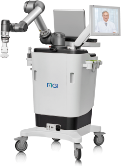
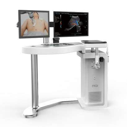
Remote control of the ultrasound probe by teleoperation is the first step to implementing robotic assistance in US scanning. The operator can control the robotic arm from a distance, be assisted by applying pressure during the scan, or even just profit from the position tracking of the robotic system. Commercial systems for teleoperated ultrasound are available, such as the MGIUS-R3 (MGI Tech Co.) system [23] or the MELODY (AdEchoTech) system [24] . These systems consist of a robotic arm with a force feedback sensor that holds the probe and can be controlled by the operator through a dummy probe up to six degrees of freedom (DOF).
Collaborative assistance is the next step towards robot autonomy. The goal is usually to assist clinicians conduct the procedures quickly, precisely, and consistently. In their work, Jiang et al. [25] improve image quality by optimizing the orientation of the RUSS probe, aligning it to the normal of the scanned tissue’s surface at the contact point. Another example is the work from Virga et al. [26], which implements an assistive control to limit the contact pressure applied on the contact surface, to estimate and correct the induced deformation. Collaborative robots can also offer therapy guidance in tasks such as needle insertion. Assistance might provide respiratory motion compensation [27] , or assist venipuncture by reconstructing and tracking a superficial vessel as shown in Chen et al. [28] using infrared sensors and automatic image segmentation. Efforts have been made to replace external force sensors with integrated torque sensors in lightweight robots, enhance motion compensation, speed real-time imaging, and improve calibration [29] .
Autonomous systems are those capable of independent task planning, control of the robot, and real-time task optimization, responding to simultaneous possible system changes. The robot must be able to adapt to the patient’s anatomy, to the probe-tissue interaction, and to the image quality. The more autonomy the robot has, the less the operator is involved in the scanning process and can therefore concentrate on interventions or diagnostic tasks. Most of the proposed solutions offer assistance for 3D image reconstruction, trajectory planning, probe positioning, or image quality optimization [29] .
The technical key developments that enable autonomous or semi-autonomous scanning from a robotic perspective is the control of three fundamental parameters: contact force, probe orientation, and scan path planning [30]. These are adjusted by the robot control system under the constraints to ensure the patient’s safety. The information necessary for path planning coming from the currently observed images and the current position must be interpreted automatically to determine the next steps.
To develop a control based on visual servoing, online access to the real-time images is necessary. This might be done by grabbing directly the frames displayed by the ultrasound system in case of 2D images. However, in the case of a 3D US scanner, the data is more complex and a streaming interface must be implemented. In addition, remote or automatic control of the imaging tuning parameters also needs to be externally developed.
Autonomous RUSS are highly application specific and have had a greater development with the rise of AI applications. In particular reliable navigation was recognized to be a missing step of research by von Haxthausen et al [29] . Different approaches to automatic path planning and navigation will be presented in RUSS Navigation Systems, drawing the motivation for a new navigation system based on the current observations, which emulates the way human sonographers perform ultrasound scans.
Bibliography#
Luca Padua, Daniele Coraci, Carmen Erra, Costanza Pazzaglia, Ilaria Paolasso, Claudia Loreti, Pietro Caliandro, and Lisa D. Hobson-Webb. Carpal tunnel syndrome: clinical features, diagnosis, and management. The Lancet. Neurology, 15(12):1273–1284, 2016. doi:10.1016/S1474-4422(16)30231-9.
Alessia Genova, Olivia Dix, Asem Saefan, Mala Thakur, and Abbas Hassan. Carpal tunnel syndrome: a review of literature. Cureus, 12(3):e7333, 2020. doi:10.7759/cureus.7333.
Michel Chammas, Jorge Boretto, Lauren Marquardt Burmann, Renato Matta Ramos, dos Santos Neto, Francisco Carlos, and Jefferson Braga Silva. Carpal tunnel syndrome - part i (anatomy, physiology, etiology and diagnosis). Revista Brasileira de Ortopedia (English Edition), 49(5):429–436, 2014. URL: https://www.sciencedirect.com/science/article/pii/S2255497114001281, doi:10.1016/j.rboe.2014.08.001.
Enzo Silvestri, Fabio Martino, and Filomena Puntillo. Ultrasound-Guided Peripheral Nerve Blocks. Springer International Publishing, Cham, 2018. ISBN 978-3-319-71019-8. doi:10.1007/978-3-319-71020-4.
L. Padua, R. Padua, M. Lo Monaco, I. Aprile, and P. Tonali. Multiperspective assessment of carpal tunnel syndrome: a multicenter study. italian cts study group. Neurology, 53(8):1654–1659, 1999. doi:10.1212/wnl.53.8.1654.
Tai-Hua Yang, Cheng-Wei Yang, Yung-Nien Sun, and Ming-Huwi Horng. A fully-automatic segmentation of the carpal tunnel from magnetic resonance images based on the convolutional neural network-based approach. Journal of Medical and Biological Engineering, 41(5):610–625, 2021. URL: https://link.springer.com/article/10.1007/s40846-021-00615-1, doi:10.1007/s40846-021-00615-1.
Mohammad Ghasemi-Rad, Emad Nosair, Andrea Vegh, Afshin Mohammadi, Adam Akkad, Emal Lesha, Mohammad Hossein Mohammadi, Doaa Sayed, Ali Davarian, Tooraj Maleki-Miyandoab, and Anwarul Hasan. A handy review of carpal tunnel syndrome: from anatomy to diagnosis and treatment. World journal of radiology, 6(6):284–300, 2014. doi:10.4329/wjr.v6.i6.284.
JENNIFER WIPPERMAN and KYLE GOERL. Carpal tunnel syndrome: diagnosis and management. American Family Physician, 94(12):993–999, 2016. URL: https://www.aafp.org/pubs/afp/issues/2016/1215/p993.html.
Cara McDonagh, Michael Alexander, and David Kane. The role of ultrasound in the diagnosis and management of carpal tunnel syndrome: a new paradigm. Rheumatology (Oxford, England), 54(1):9–19, 2015. doi:10.1093/rheumatology/keu275.
K. Kanagasabai. Ultrasound of median nerve in the diagnosis of carpal tunnel syndrome-correlation with electrophysiological studies. The Indian Journal of Radiology & Imaging, 32(1):16–29, 2022. URL: https://www.ncbi.nlm.nih.gov/pmc/articles/PMC9203152/, doi:10.1055/s-0041-1741088.
Sandy C. Takata, Lynn Kysh, Wendy J. Mack, and Shawn C. Roll. Sonographic reference values of median nerve cross-sectional area: a protocol for a systematic review and meta-analysis. Systematic Reviews, 8(1):2, 2019. URL: https://link.springer.com/article/10.1186/s13643-018-0929-9, doi:10.1186/s13643-018-0929-9.
Maureen Wilkinson, Karen Grimmer, and Nicola Massy-Westropp. Ultrasound of the carpal tunnel and median nerve. Journal of Diagnostic Medical Sonography, 17(6):323–328, 2001. doi:10.1177/875647930101700603.
Robert A. Werner and Michael Andary. Electrodiagnostic evaluation of carpal tunnel syndrome. Muscle & nerve, 44(4):597–607, 2011. doi:10.1002/mus.22208.
Alex Freitas. Basic-wrist-mri. 2/15/2024. URL: https://freitasrad.net/pages/Basic_MSK_MRI/basic-wrist-mri.php (visited on 2/15/2024).
Christoph F. Dietrich, Claude B. Sirlin, Mary O'Boyle, Yi Dong, and Christian Jenssen. Editorial on the current role of ultrasound. Applied Sciences, 9(17):3512, 2019. URL: https://www.mdpi.com/2076-3417/9/17/3512, doi:10.3390/app9173512.
K. Kirk Shung. Diagnostic ultrasound: Past, present, and future. J Med Biol Eng 31.6, 2011. URL: https://citeseerx.ist.psu.edu/document?repid=rep1&type=pdf&doi=f569429cd4494912656601f25dcc50f978e280e5.
Mohammad Ali Maraci, Raffaele Napolitano, Aris Papageorghiou, and J. Alison Noble. Searching for structures of interest in an ultrasound video sequence. In Guorong Wu, Daoqiang Zhang, and Luping Zhou, editors, Machine Learning in Medical Imaging, volume 8679 of Image Processing, Computer Vision, Pattern Recognition, and Graphics, 133–140. Cham, 2014. Springer International Publishing and Imprint: Springer. URL: https://link.springer.com/chapter/10.1007/978-3-319-10581-9_17, doi:10.1007/978-3-319-10581-9{\textunderscore }17.
Kevin Evans, Shawn Roll, and Joan Baker. Work-related musculoskeletal disorders (wrmsd) among registered diagnostic medical sonographers and vascular technologists. Journal of Diagnostic Medical Sonography, 25(6):287–299, 2009. doi:10.1177/8756479309351748.
Shawn C. Roll, Lauren Selhorst, and Kevin D. Evans. Contribution of positioning to work-related musculoskeletal discomfort in diagnostic medical sonographers. Work, 47(2):253–260, 2014. doi:10.3233/WOR-121579.
Jenay M. Beer, Arthur D. Fisk, and Wendy A. Rogers. Toward a framework for levels of robot autonomy in human-robot interaction. Journal of human-robot interaction, 3(2):74–99, 2014. doi:10.5898/JHRI.3.2.Beer.
MGIUS-R3. Mgius-r3 robotic ultrasound system-mgi tech website-leading life science innovation. 7/22/2024. URL: https://en.mgitech.cn/products/instruments_info/11/ (visited on 7/22/2024).
AdEchoTech. Melody, a remote, robotic ultrasound solution. 10/9/2023. URL: https://www.adechotech.com/products/ (visited on 10/9/2023).
Zhongliang Jiang, Matthias Grimm, Mingchuan Zhou, Javier Esteban, Walter Simson, Guillaume Zahnd, and Nassir Navab. Automatic normal positioning of robotic ultrasound probe based only on confidence map optimization and force measurement. IEEE Robotics and Automation Letters, 5(2):1342–1349, 2020. doi:10.1109/LRA.2020.2967682.
Salvatore Virga, Rüdiger Göbl, Maximilian Baust, Nassir Navab, and Christoph Hennersperger. Use the force: deformation correction in robotic 3d ultrasound. International Journal of Computer Assisted Radiology and Surgery, 13(5):619–627, 2018. URL: https://link.springer.com/article/10.1007/s11548-018-1716-8, doi:10.1007/s11548-018-1716-8.
Dongrui Li, Zhigang Cheng, Gang Chen, Fangyi Liu, Wenbo Wu, Jie Yu, Ying Gu, Fengyong Liu, Chao Ren, and Ping Liang. A multimodality imaging-compatible insertion robot with a respiratory motion calibration module designed for ablation of liver tumors: a preclinical study. International journal of hyperthermia : the official journal of European Society for Hyperthermic Oncology, North American Hyperthermia Group, 34(8):1194–1201, 2018. doi:10.1080/02656736.2018.1456680.
Alvin I. Chen, Max L. Balter, Timothy J. Maguire, and Martin L. Yarmush. 3d near infrared and ultrasound imaging of peripheral blood vessels for real-time localization and needle guidance. In Sébastien Ourselin, Leo Joskowicz, Mert R. Sabuncu, Gozde Unal, and Williams Wells, editors, Medical Image Computing and Computer-Assisted Intervention – MICCAI 2016, Lecture Notes in Computer Science, 388–396. Cham, 2016. Springer International Publishing. URL: https://link.springer.com/chapter/10.1007/978-3-319-46726-9_45, doi:10.1007/978-3-319-46726-9{\textunderscore }45.
Felix von Haxthausen, Sven Böttger, Daniel Wulff, Jannis Hagenah, Verónica García-Vázquez, and Svenja Ipsen. Medical robotics for ultrasound imaging: current systems and future trends. Current Robotics Reports, 2(1):55–71, 2021. URL: https://link.springer.com/article/10.1007/s43154-020-00037-y, doi:10.1007/s43154-020-00037-y.
Zhongliang Jiang, Septimiu E. Salcudean, and Nassir Navab. Robotic ultrasound imaging: state-of-the-art and future perspectives. Medical Image Analysis, 89:102878, 2023. URL: https://www.sciencedirect.com/science/article/pii/S136184152300138X, doi:10.1016/j.media.2023.102878.
Mariya Baby and A.S Jereesh. Automatic nerve segmentation of ultrasound images. In ICECA, editor, Proceedings of the International Conference on Electronics, Communication and Aerospace Technology (ICECA 2017), 107–112. Piscataway, NJ, 2017. IEEE. doi:10.1109/ICECA.2017.8203654.
Chueh-Hung Wu, Wei-Ting Syu, Meng-Ting Lin, Cheng-Liang Yeh, Mathieu Boudier-Revéret, Ming-Yen Hsiao, and Po-Ling Kuo. Automated segmentation of median nerve in dynamic sonography using deep learning: evaluation of model performance. Diagnostics (Basel, Switzerland), 2021. doi:10.3390/diagnostics11101893.
Mariachiara Di Cosmo, Maria Chiara Fiorentino, Francesca Pia Villani, Emanuele Frontoni, Gianluca Smerilli, Emilio Filippucci, and Sara Moccia. A deep learning approach to median nerve evaluation in ultrasound images of carpal tunnel inlet. Medical & Biological Engineering & Computing, 60(11):3255–3264, 2022. URL: https://link.springer.com/article/10.1007/s11517-022-02662-5, doi:10.1007/s11517-022-02662-5.
Gianluca Smerilli, Edoardo Cipolletta, Gianmarco Sartini, Erica Moscioni, Mariachiara Di Cosmo, Maria Chiara Fiorentino, Sara Moccia, Emanuele Frontoni, Walter Grassi, and Emilio Filippucci. Development of a convolutional neural network for the identification and the measurement of the median nerve on ultrasound images acquired at carpal tunnel level. Arthritis research & therapy, 24(1):38, 2022. doi:10.1186/s13075-022-02729-6.
Risto Kojcev, Ashkan Khakzar, Bernhard Fuerst, Oliver Zettinig, Carole Fahkry, Robert DeJong, Jeremy Richmon, Russell Taylor, Edoardo Sinibaldi, and Nassir Navab. On the reproducibility of expert-operated and robotic ultrasound acquisitions. International Journal of Computer Assisted Radiology and Surgery, 12(6):1003–1011, 2017. URL: https://link.springer.com/article/10.1007/s11548-017-1561-1, doi:10.1007/s11548-017-1561-1.
Fausto Milletari, Vighnesh Birodkar, and Michal Sofka. Straight to the point: reinforcement learning for user guidance in ultrasound. In Smart Ultrasound Imaging and Perinatal, Preterm and Paediatric Image Analysis: First International Workshop, SUSI 2019, and 4th International Workshop, PIPPI 2019, Held in Conjunction with MICCAI 2019, Shenzhen, China, October 13 and 17, 2019, Proceedings 4, 3–10. Springer, Cham, 2019. URL: https://link.springer.com/chapter/10.1007/978-3-030-32875-7_1, doi:10.1007/978-3-030-32875-7{\textunderscore }1.
Volodymyr Mnih, Koray Kavukcuoglu, David Silver, Andrei A. Rusu, Joel Veness, Marc G. Bellemare, Alex Graves, Martin Riedmiller, Andreas K. Fidjeland, Georg Ostrovski, Stig Petersen, Charles Beattie, Amir Sadik, Ioannis Antonoglou, Helen King, Dharshan Kumaran, Daan Wierstra, Shane Legg, and Demis Hassabis. Human-level control through deep reinforcement learning. Nature, 518(7540):529–533, 2015. URL: https://www.nature.com/articles/nature14236, doi:10.1038/nature14236.
Hannes Hase, Mohammad Farid Azampour, Maria Tirindelli, Magdalini Paschali, Walter Simson, Emad Fatemizadeh, and Nassir Navab. Ultrasound-guided robotic navigation with deep reinforcement learning. In 2020 IEEE/RSJ International Conference on Intelligent Robots and Systems (IROS), 5534–5541. IEEE, 2020. doi:10.1109/IROS45743.2020.9340913.
Kaiming He, Xiangyu Zhang, Shaoqing Ren, and Jian Sun. Deep residual learning for image recognition. URL: http://arxiv.org/pdf/1512.03385.
Yuwei Li, Minye Wu, Yuyao Zhang, Lan Xu, and Jingyi Yu. Piano: a parametric hand bone model from magnetic resonance imaging. In Zhi-Hua Zhou, editor, Proceedings of the Thirtieth International Joint Conference on Artificial Intelligence, IJCAI-21, 816–822. 2021. doi:10.24963/ijcai.2021/113.
Yuan Bi, Zhongliang Jiang, Yuan Gao, Thomas Wendler, Angelos Karlas, and Nassir Navab. Vesnet-rl: simulation-based reinforcement learning for real-world us probe navigation. IEEE Robotics and Automation Letters, 7(3):6638–6645, 2022. doi:10.1109/LRA.2022.3176112.
Christian F. Baumgartner, Konstantinos Kamnitsas, Jacqueline Matthew, Tara P. Fletcher, Sandra Smith, Lisa M. Koch, Bernhard Kainz, and Daniel Rueckert. Sononet: real-time detection and localisation of fetal standard scan planes in freehand ultrasound. IEEE transactions on medical imaging, 36(11):2204–2215, 2017. doi:10.1109/TMI.2017.2712367.
Laura Bartha, Andras Lasso, Csaba Pinter, Tamas Ungi, Zsuzsanna Keri, and Gabor Fichtinger. Open-source surface mesh-based ultrasound-guided spinal intervention simulator. International Journal of Computer Assisted Radiology and Surgery, 8(6):1043–1051, 2013. URL: https://link.springer.com/article/10.1007/s11548-013-0901-z, doi:10.1007/s11548-013-0901-z.
Shuangyi Wang, James Housden, Tianxiang Bai, Hongbin Liu, Junghwan Back, Davinder Singh, Kawal Rhode, Zeng-Guang Hou, and Fei-Yue Wang. Robotic intra-operative ultrasound: virtual environments and parallel systems. IEEE/CAA Journal of Automatica Sinica, 8(5):1095–1106, 2021. doi:10.1109/JAS.2021.1003985.
Keyu Li, Xinyu Mao, Chengwei Ye, Ang Li, Yangxin Xu, and Max Q. -H Meng. Style transfer enabled sim2real framework for efficient learning of robotic ultrasound image analysis using simulated data. URL: http://arxiv.org/pdf/2305.09169.pdf.
Yordanka Velikova, Walter Simson, Mehrdad Salehi, Mohammad Farid Azampour, Philipp Paprottka, and Nassir Navab. Cactuss: common anatomical ct-us space for us examinations. In Linwei Wang, editor, Medical Image Computing and Computer Assisted Intervention - MICCAI 2022 : 25th International Conference, Singapore, September 18-22, 2022, Proceedings, Part III, 492–501. Springer, 2022. URL: https://link.springer.com/chapter/10.1007/978-3-031-16437-8_47, doi:10.1007/978-3-031-16437-8{\textunderscore }47.
Taesung Park, Alexei A. Efros, Richard Zhang, and Jun-Yan Zhu. Contrastive learning for unpaired image-to-image translation. URL: http://arxiv.org/pdf/2007.15651.
Yordanka Velikova, Mohammad Farid Azampour, Walter Simson, Vanessa Gonzalez Duque, and Nassir Navab. Lotus: learning to optimize task-based us representations. In Hayit Greenspan, Anant Madabhushi, Parvin Mousavi, Septimiu Salcudean, James Duncan, Tanveer Syeda-Mahmood, and Russell Taylor, editors, Medical Image Computing and Computer Assisted Intervention - MICCAI 2023, volume 14220 of Lecture Notes in Computer Science, pages 435–445. Springer Nature Switzerland, Cham, 2023. doi:10.1007/978-3-031-43907-0{\textunderscore }42.
